![]()
Currently the radio amateur lacks a cohesive and uniform method of providing computer control for all the various pieces of equipment utilized in an amateur radio station. As the ubiquitous PC has now become a standard piece of equipment in the typical amateur station, it is becoming more important to be able to connect it easily to equipment in the ham shack.
There lacks any standardized interface method for being able to control radios and other pieces of amateur radio equipment. Many radios do have the capability to be connected to a PC but the protocols used are proprietary and vary greatly between manufacturer, and even between models from the same manufacturer. The RS232 serial port is being supplanted by newer interfaces such as USB, IEEE1394, and Ethernet connections making the interface matrix even more complicated. In addition, many new modes are being developed using soundcards adding yet another interfacing issue into the mix.
This lack of standards is a major obstacle in allowing future development of more applications that could take advantage of station control capabilities and introduce exciting new advances in amateur radio station operation. There has been much talk of developing the concept of the SDR(Software Defined Radio) and in order to successfully develop this new paradigm, some standards will be needed to implement the ideas.
To this end, this project tries to address the problem from a global view and offer a possible development path to provide a uniform station control protocol.
Protocol Goals
In order to be as generic as possible and allow maximum flexibility, the interface protocol needs to be placed where it meets the following criteria:
It is vital not to design a protocol that depends on any particular operating system or language. The protocol needs to be open and be operable with existing as well as future operating systems that may come along.
The protocol needs to be compatible with as many hardware physical signaling methods as possible. It should be able to be transported over most of the existing connection links such as Ethernet, USB, IEEE1394, as well as simple RS-232 serial links.
The protocol must strike a fair balance between simplicity and complexity to allow for as wide a range of applications as possible. For example, it must be useable for a simple application such as a remote antenna switch that may contain a very primitive microcontroller. On the other hand, it must be rich enough to allow for complicated control scenarios where multiple radios, antenna configurations, and software configurable devices are all connected in one station.
The development of the protocol must be done with as much input from as many developers as possible in order to utilize the expertise of as many as possible. This will help insure that it will be as useable for as many different applications as possible.
![]()
ASCP Description
PurposeThis specification addresses the need for a common, generic way to control and monitor an amateur radio station remotely using a standardized protocol. The protocol is operating system and hardware neutral in that it only defines a set of byte blocks that can be received and transmitted through any existing physical medium such as Ethernet, USB, IEEE1394, RS232, or other byte oriented scheme. There are no operating system specific functions or methods so it can be used with any OS.
In addition to control functionality, the protocol allows for the exchange of raw data over the same link such as digitized audio, I/Q signals, AX25 packet data, etc.
Definitions used in this specification:
Host == The main initiator of communications. Typically would be a PC or other computer system such as a custom user interface controller.
Target == The device that is to be controlled or monitored by the Host.
Control Item == The value, setting, or state of the target that is to be controlled or monitored by the Host. For example Frequency, Antenna direction, modulation mode, transmitter state, etc.
Data Item
== Digital data associated with the received or transmitted signal. This could be digitized audio, IF, frequency domain data(FFT), information data such as text or AX25 data, etc.Message Block == A contiguous block of bytes comprising a single Control Item or Data Item transfer from target to host or host to target.
To simplify the protocol, the link can only comprise one host and one target. The Host is the only one that can set or request Control items. This means a Target device cannot connect to another target device or daisy chain to other targets. The Host can control multiple Targets by utilizing multiple links such as USB endpoints or multiple TCP/IP Sockets.
The protocol allows a Target to send unsolicited Control Item messages to the Host. This is desirable for updating the Host when a something changes in the Target without the need for polling by the Host. An example would be when a user changes the frequency of the radio using the radio's frequency knob. The target can send the updated frequency as it occurs without requiring the Host to ask for it.
Message blocks contain the block length in the message header. This is useful to aid in decoding messages as well as being able to support variable length Control Items. For example, a Control Item containing the text string for the Target's manufacturer and model number can be different lengths.
The protocol contains a mechanism for obtaining information about the range and resolution of a Control Item. This allows the Host to obtain the limits of Control Items for the particular target device. For example, the frequency ranges of the target as well as the frequency step size can be obtained without any knowledge of the model or manufacturer of the radio. This capability is key in being able to write a generic application interface program without having to maintain a list of all possible radios and devices that may be connected.
Target devices are not required to implement all the functionality of the protocol. A simple Target device that turns on and off a light need only implement the single Control Item message associated with it. This allows micro controllers with limited capability to be used.
The Data Item message blocks allow various raw data blocks to be sent and received along with the Control Items over the same physical link. The Header type allows up to 5 logical channels of data to be specified in each direction. This permits sending digitized audio, digitized I/Q IF data, etc. to and from a target over the same physical connection.
Note that there is no synchronization or error handling mechanism in this protocol. This layer of protocol assumes that the block synchronization and error handling is done at a lower level. This is a reasonable assumption since Ethernet, USB, IEEE 1394, and most other modern physical links provide robust error recovery. The exception is RS232 serial links. This protocol will work over it as-is but if any data corruption is anticipated, then some simple method such as "SLIP" should be used to frame the data bytes and perhaps add error detection as well. A little "sanity" checking of message block parameters can be used as a simple error detection scheme and allow the RS232 system to eventually sync back up. Since RS232 serial links are being phased out, it doesn't make sense to burden a protocol to handle such a legacy physical link.
The basic message structure starts with a 16 bit header that contains the length of the block in bytes and also a 3 bit type field. If the message is a Control Item, then a 16 bit Control Item code follows the header and contains the code describing the object of the message block. This is followed by an optional number of parameter or data bytes associated with this message. The byte order for all fields greater than 8 bits is "Little Endian" or least significant byte first.
Control Item Message block format:
|
16 bit Header(lsb msb) |
16 bit Control Item(lsb msb) |
Parameter Bytes |
Data Item Message block format:
|
16 bit Header(lsb msb) |
N-Data Bytes |
The 16 bit header is defined as follows:
|
8 bit Length lsb |
3 bit type |
5 bit Length msb |
The 13 bit Length parameter value is the total number of bytes in the message including this header. The range of the message Length is 0 to 8192 bytes.
A special case for Data Items is that a message length of Zero is used to specify an actual message length of 8194 bytes. This allows data block sizes of a power of 2 to be used which is useful in dealing with FFT data.
A 16 bit header containing no Control Item or parameters is a special case and is called a NAK message.
The message type field is used by the receiving side to determine how to process this message block. It has a different meaning depending upon whether the message is from the Host or Target.
|
3 bit Msg Type field |
Message Source |
Message Type |
|
000 |
Host |
Set Control Item |
|
001 |
Host |
Request Current Control Item |
|
010 |
Host |
Request Control Item Range |
|
011 |
Host |
Host Data Item 0 |
|
100 |
Host |
Host Data Item 1 |
|
101 |
Host |
Host Data Item 2 |
|
110 |
Host |
Host Data Item 3 |
|
111 |
Host |
Host Data Item 4 |
|
000 |
Target |
Response to Set or Request Current Control Item |
|
001 |
Target |
Unsolicited Control Item |
|
010 |
Target |
Response to Request Control Item Range |
|
011 |
Target |
Target Data Item 0 |
|
100 |
Target |
Target Data Item 1 |
|
101 |
Target |
Target Data Item 2 |
|
110 |
Target |
Target Data Item 3 |
|
111 |
Target |
Target Data Item 4 |
|
|
|
|
Set Control Item
This Message type is sent from the Host to the Target requesting that the Target change the specified Control Item to the new value supplied in this message. A request to change to a new frequency would be an example of this type of message. The Target must respond to this message.
This Message type is sent from the Host to the Target requesting that the Target respond with its current state or value of the specified Control Item of this message. A request to get the current S-meter reading would be an example of this message type. The Target must respond to this message.
This Message type is sent from the Host to the Target requesting that the Target respond with the acceptable range of values of the Control Item supplied in this message. A request for the targets frequency range(s) and step sizes would be an example of this message type. The Target must respond to this message.
This Message type is sent from the Target to the Host in response to a request from the Host to either set or just return the current value of the Control Item supplied in this message. This message contains the current value of the Control Item. It is sent in response to either the "Set Control Item" or "Request Control Item" message.
This Message type can be sent from the Target to the Host without any request from the Host. It contains the current value of the Control Item supplied in this message. This message can be sent at any time to the Host. It can be used to update the Host to any changes that have occurred in the Target Control Items. An example would be if the user changed frequency using the Targets frequency knob, then the Target could send the new Control Item value to the Host without having to wait for the Host to ask for it. There is no response back from the Host when this message is received.
This Message is sent from the Target to the Host in response to a "Request Control Item Range" message from the Host. It contains the allowable range and step size of the Control Item supplied in this message.
Data Item message allow data messages to be allocated to different logical "channels". Different types of data blocks may be interleaved together and this mechanism allows each end to keep the data separated. For example, Data Item 3 blocks may be digitized audio from a Target receiver that needs to be processed and sent to a soundcard speaker. Data Item 2 Blocks may be spectral data from an FFT inside the Target receiver that needs to be sent to the Host applications display screen.
The current scheme allows up to five different logical channels for each data direction.
A "NAK" message is a 16 bit header without a Control Item or parameters (Message length of 2). When the NAK message block is returned by the Target, it indicates that the specified Control Item is not supported. This allows a target to implement only the Control Items it actually needs. Any Host message requesting an unimplemented Control Item will be returned the NAK message. The Host can then exclude this Control Item from its list of Items to control or monitor.
As an example, suppose a Host requests the elevation setting from a rotor Target controller that only supports azimuth readings. The Target controller would just return the NAK header.
Implementation on the Target side is easily done by simply decoding only the Control Item messages that it supports and returning the NAK for all others.
On the Host side, one could initially poll the Target for all the Control Items it may use and then tag the ones that return NAK for exclusion.
This dynamically allocated feature set allows application software to determine on the fly what capabilities are available without any prior knowledge of the Target device.
The "NAK" message could also be used with Data Items and perhaps redefined as an ACK for data messages. This issue remains undetermined at this time.
![]()
An incomplete super-pre-initial-release ragged start to defining a spec
ASCPSpec017.pdf (127K)
![]()
ASCP Based Projects
Two ongoing projects are using this ASCP concept to validate the protocol as well as maybe provide some useful hardware/software solutions.
WinXcv -- A Windows based transceiver program that interfaces with various hardware platforms such as the DSP-10.
A Wide band Spectrum capture project -- http://www.rfspace.com/
Early Prototype Hardware---
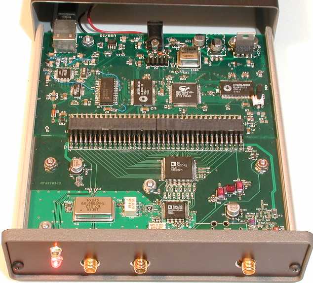
Screen shot of 20 Meter activity and a funky carrier moving around the band---
