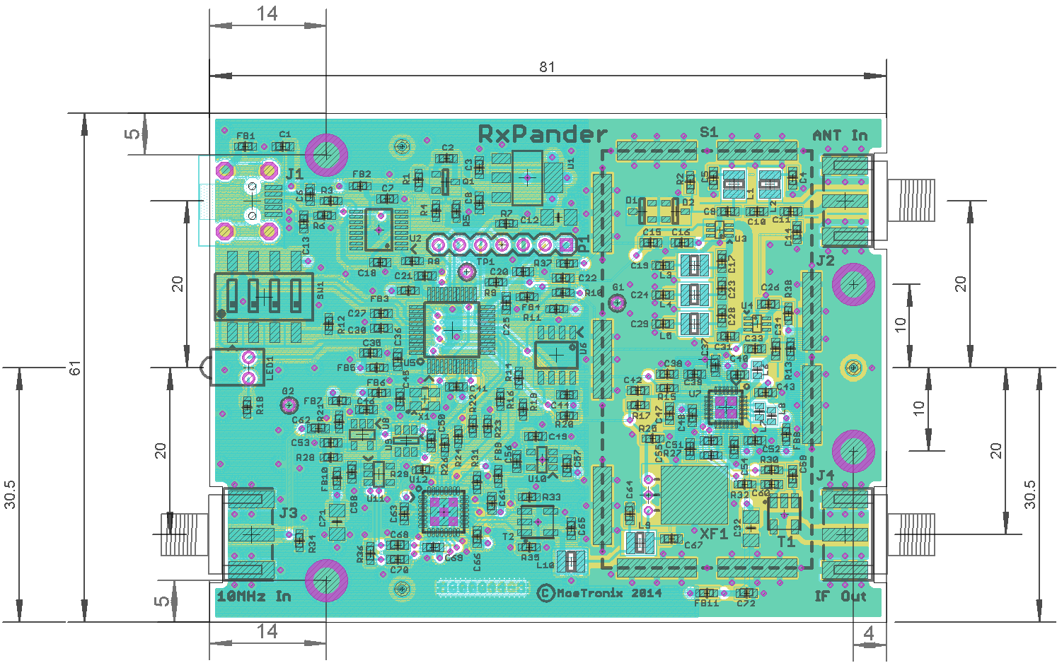
RxPander
Project
A VHF/UHF to 5MHz Down
Converter Board
Update (2014-07-14) -- Starting Re-layout board to be able to use shield over RF components.
Update
(2014-08-08) -- Rev 2 was a bust. The shield did not help with
spurs. It appears they are coming from the power planes and
radiation from 10MHz clock traces.
New
Rev 3 layout attempts to bury clock lines inbetween ground planes and
beads to all power pins. Also changed the DDS clock to LVDS balanced
drive to try and improve phase noise. Changed all connectors to
SMA. Filters all logic signals going to RF section. If this
doesn't work then the project willl be abandoned.
2014 SVHFS Conference Presentation (3.6M .pdf)
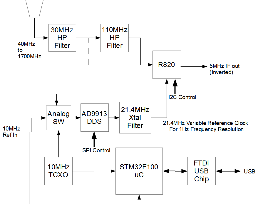
- Input 40 to
1700MHz and converts to 5MHz IF Frequency
- USB Virtual Serial
port supplies power and frequency control
- 8MHz IF Bandwidth
- ~1Hz Frequency
Resolution
- External 10MHz
reference option
- <10dB NF
- ~65dB Image
rejection
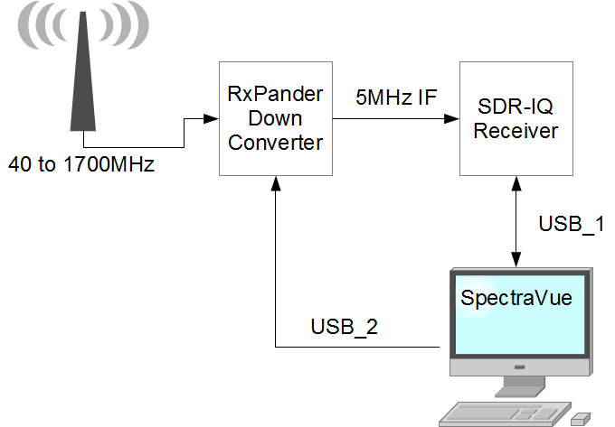
Typical User Setup
RxPander Block Diagram
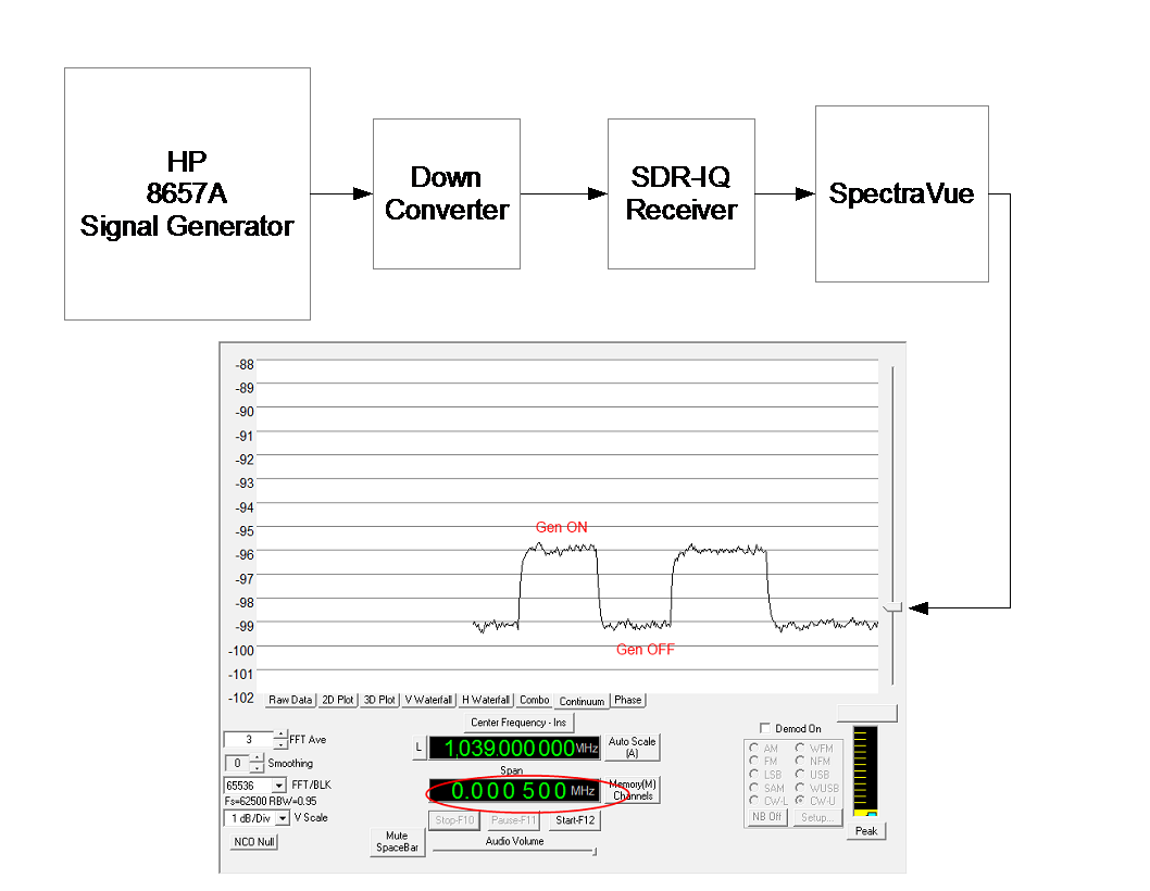
Sensitivity Measurement Method
MDS = -174dBm/Hz + NF(dB) + 10log BW (Hz)
Insert a carrier until the power in a specified bandwidth is doubled. S=N
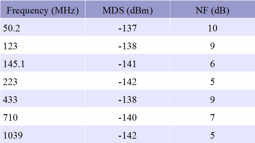
Sensitivity Measurement Results
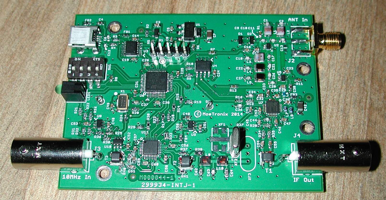
First Rev 1 Proto Board
In Hammond Case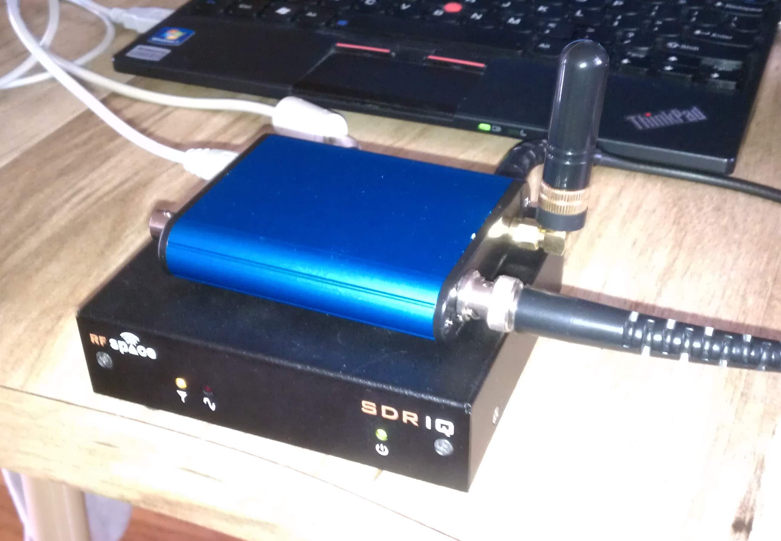
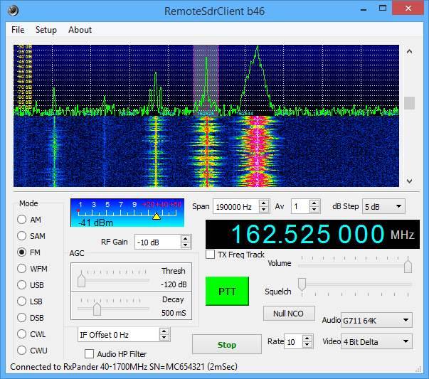
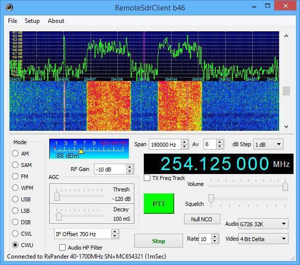
Example Uses
Using RxPander with SDR-IQ Client-Server over Internet:
Atlanta Area Weather Stations and a Military Satellite
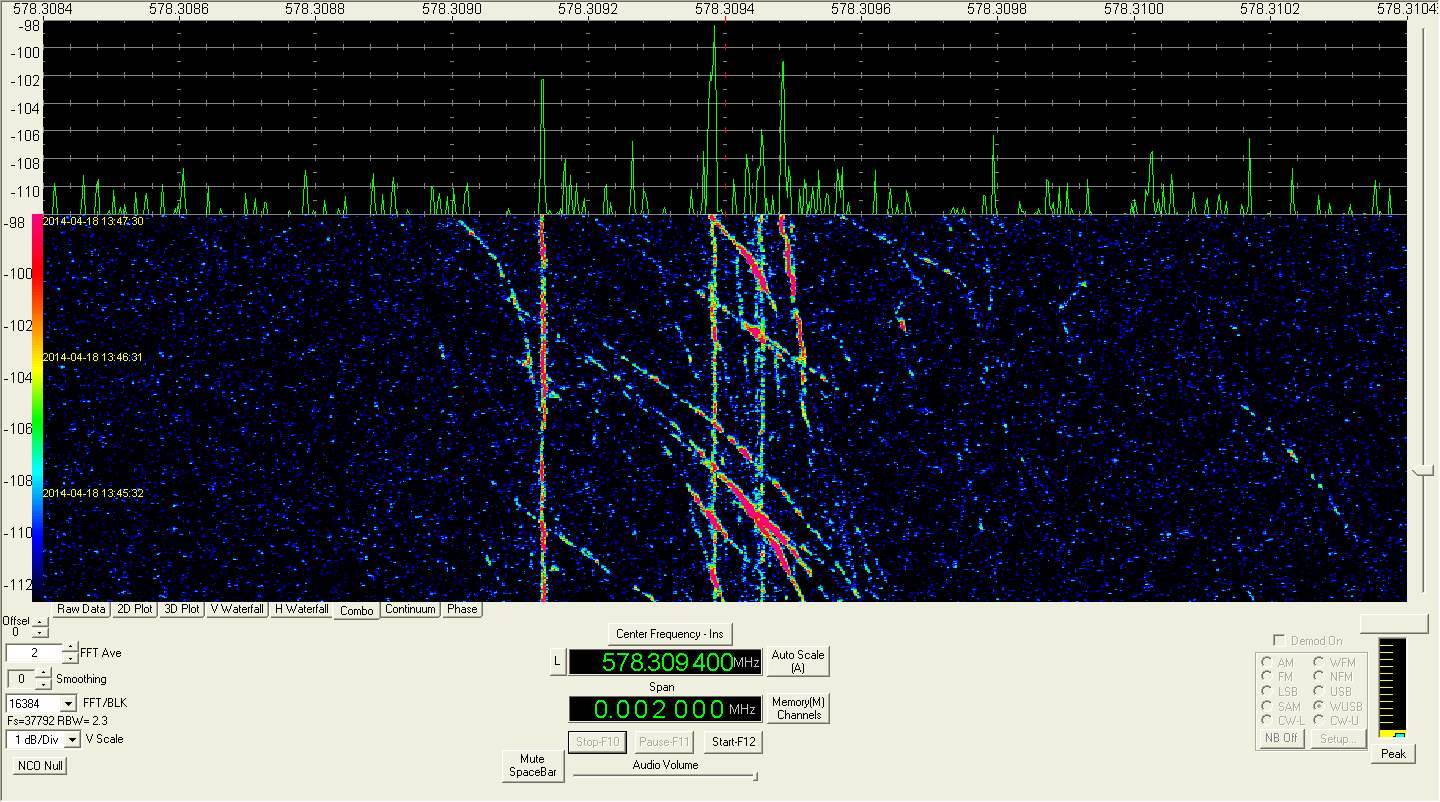
Passive Aircraft Radar Using HDTV Channel 32 ATSC Pilot signal just over the horizon:
Current Status:
- Re-layout to reduce cost and add RF shield (2014-7-20)